Stormworks:Build and Rescue – エンジンの設計ガイド (封じ込められた爆発を最大限に活用する方法)

このガイドは、ほとんどの状況で効果的なエンジンを設計する方法を示すことを目的としています!
エンジン設計ガイド
はじめに
- これは、ギアボックスに関する他のガイドの論理的な続きです。
ギアボックスがどのように機能するかを既に理解している場合、および/またはギアボックスを深く掘り下げる気がない場合は、明示的に読む必要はありません。エンジンの基本セクションを含め、そこでカバーされているものと同じことはカバーしないようにします.
だから、エンジン。それらは、Stormworks のすべてのビルドの大部分で避けられない部分です。基本モードとは異なり、どこにでも移動するにはエンジンに車両の約半分の質量が必要なため、高度なモードを扱います!
このガイドでは、エンジン アセンブリの絶対的な基本、つまり、空気、クーラント、燃料、排気、動力を接続する方法を理解し、ギアボックス、クラッチ、発電機コンポーネントの基本機能を理解していることを前提としています。
エンジンの紹介
このセクションでは、ジェット エンジンについては説明しません。これは、ジェット エンジンが他のエンジンと比べて根本的にどのように機能するかが大きく異なるためです。将来的には独自のセクションを持つ可能性があります。
エンジンには基本的に 3 つの異なる種類がありますが、以下に見落としがあります:
純燃焼エンジン
サイズは 3 種類あります:小、大、「なんてことだ」。 3 つの異なるサイズの主な違いは 3 つあります。接続方法、「スイート スポット」(後述)、およびトルク値です。
すべてのエンジンは同じ量の RPS を提供できますが、これは近い将来変更されるとはっきりと感じています。このガイドの長さから明らかなことがありますが、エンジンの仕組みは実にシンプルです。
長所:
- 電力消費は最小限です。
- 発電機/オルタネーターを必要とせず、必要に応じてエンジン パフォーマンスの一部のみを使用できます。
- ほとんどの場合、エンジンのパフォーマンスは簡単に予測できます。
- セットアップがかなり簡単。
- (非常に) 軽いセットアップで軽量。
短所:
- すべてのエンジン タイプで最大の燃料消費
- 設計ミスを起こしやすい
- 文字通り大量の燃料が必要なため、大量のパワーが必要な場合は重くなります。
- 失速しやすい。
ハイブリッド / 電動アシスト ドライブ
これらは根本的に異なる 2 つのドライブですが、機能が似ているため、同じカテゴリに分類します。
ハイブリッド ドライブは、バッテリーが高くなると電気駆動がアクティブになり、バッテリーが少なくなると電気駆動を切り離して、バッテリーを再充電し、燃料エンジンをオンにします。目標は燃料消費量の削減です。
電動アシスト ドライブは、エンジンと連動して常時作動し、トルクを高めます。非常に強力なエンジンを小さなパッケージに収める方法の 1 つです。通常、これは燃費に悪影響を及ぼしますが、多くの調整を行うと、燃費にほとんど影響を与えない可能性があります。
長所:
- 技術的に失速の影響を受けません (電動アシスト / 電気モードのみ)。
- 発電能力が高い
- そのサイズのカテゴリーをはるかに超えるトルク (電動アシスト) を打ち破ることができます。
- 非常に低燃費 (ハイブリッド ドライブ)。
- 比較的簡単なセットアップ (電動アシスト)
- 増加する車両のトン数に合わせてスケーリングします。
短所:
- 電池切れに弱い(落雷もある)
- 従来の燃焼エンジン (特にハイブリッド) よりも複雑な設計
- 軽自動車 (特にハイブリッド ドライブ) では過度に重い。
- 多くのバッテリーは重量があります (バッテリーをバラストとして利用できる場合はニュートラルになる可能性があります)。
ディーゼル発電機を備えた純粋な電気駆動
(説明のための例であり、実際にはこれほど単純には機能しません)
非常に大型の貨物船や、バックアップ発電機としての一部の新しい電気自動車で一般的なセットアップです。通常はより大きなエンジンを使用して電力を生成し、その電力を別の場所で使用します。
長所:
- 最適化すると燃料消費量が非常に少なくなります。
- エンジンを簡単に最適化して、必要に応じて発電機を提供できる
- 必要な場所にエンジンと燃料を配置できる一方で、推進力はわずかなスペースしか必要としません。
- 失速することは絶対にありません。
- 比較的簡単なセットアップ
短所:
- 他のオプションに比べて圧倒的に重い
- さらに多くのバッテリーが必要で、さらに重くなります。
燃焼の基礎 (単純な要因)
このセクションはデータとしてのみ保持します。このゲームでディーゼル エンジンがどのように機能するかについて、基本的なことがいくつかあります。
これらはすべて燃焼エンジンを使用するため、設計上の決定について混乱している場合は、ここを参照してください。
熱
- エンジンの加熱率は、RPS 値に直接関係しています。
- 液体 (できれば水) を送り込むことで熱を下げることができます。
- より多くの液体を送り込むことで、この熱の減少を増やすことができます。
出力
- エンジンのトルク出力は RPS とともに上昇します。
- RPS は可変ですが、ギアボックスによってさらに変更できます。
- エンジンにかかる負荷に基づいて、エンジンの最大可能な RPS が低下します。
- クラッチを介してエンジンを部分的にしか接続しないようにすることで、負荷が軽減され、より高い RPS が可能になります。
燃料
- エンジンは負荷に応じて燃料を消費しません。
- エンジンは RPS に基づいて燃料を消費します。より多くの RPS、より多くの消費
排気
一見大した問題ではなく、自由に出力できる以上、排気量が足りているかどうかはエンジンを見て正しく測定するしかありません。視覚的には、より多くの排気管に向けない限り、煙のプルームが濃くなります。
空気
エンジンの RPS を増やすには、より多くの空気が必要ですが、コンプレッサーを使用しなくても信じられないほどの量の空気を吸い込むことに問題はありません
このチェックリストとこのチェックリストだけを使用して、あらゆるタイプと種類のエンジンを設計できます。
ボート エンジンの設計 (燃焼のみ)
ねえ、恐竜を爆発させてボートを前進させたらどうなる?!
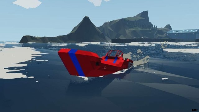
私たちは、私のこの古くて骨の折れたスピードボートのデザインを使用するつもりです.これはバージョン 0.4 前後に作られた老犬で、ゲーム開発の観点から言えば 80 年代の揺るぎないものです。
これはビルドに沿ったものなので、Stormworks をロードして始めましょう!
恐ろしい理論セクション (実際には短い)
「戦いに負けた将軍は、事前にいくつかの計算を行います。 「孫子、兵法
はい、私はあなたに孫子の知恵を落としています (そして、実際よりも長く見えるようにこれをパディングします)。
負荷 (エンジンが動作しているもの) を処理します。プロペラは水中で最も重く、推進力しか与えられません。プロペラの回転を妨げているのは、体の抵抗だけです。このことから、一定の負荷を扱っていることがわかります (プレーニング以外で!)。
- これは事実上、ギアが 1 つあればまったく問題ないことを意味します。
- 文字通り無限の冷却剤があります。クーラント タンクは必要ありません。海水を直接使用できます
第二の理論セクション
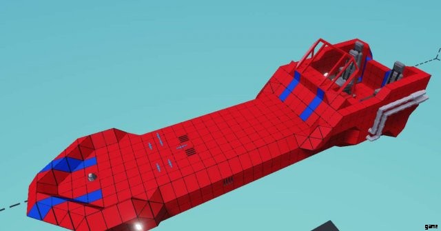
さて、特定のデザインのボートを作っているので、ボートが水上でどのように機能するか、より具体的には、このボートが水上でどのように機能するかを考えてみましょう.
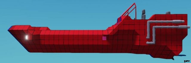
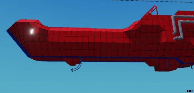
これはボートを横から見たものです。右側に一対の支柱があり、質量の中心がピンク色で表示されています (既にエンジンを追加しました)。これだけで十分です。画像に MS ペイントを適用させてください。
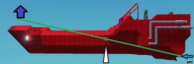
重心は、シーソーの支点(テコの中点)のような働きをします。推力の中心 (青い矢印) は質量の中心よりも下にあるため、機首が持ち上がります (薄い紫色の矢印)。これはスピードボートでは望ましいことですが、それ以外の場合は望ましくありません。水は空気よりも動き (抗力) に対する抵抗が大きく、これも揚力の原因となるため、船首も水から浮き上がろうとします。
大型の商用車では、プロペラはしばしば角度が付けられているため、このような上向きのバウリフトは提供されません.ボートでは、この揚力を減らすために、ほとんどの重量を前方にかけるのが一般的です。これにより、はるかに制御しやすく、扱いやすくなります。
私はすべての仮説を立てました。次はどうしますか?
理論は、これらの小さな設計上の課題についてどのように考えるかを学ぶためのものであり、それを飛ばすことができる人もいれば、それについて考える必要がある人もいます.通常、デザインをウィングできるようになるには練習が必要です。
ボートには、船体とコックピット、燃料タンク、排気システムがあらかじめ用意されています。それ以外はすべて作成します。
さて、いくつかのものを作ります
何かを作る
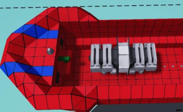
2つのエンジンが必要になります。それらを前方に向けて配置します。それらをどのように配置するかはあなた自身の呼び出しであり、それらをどこに配置するかはあなた自身の呼び出しです。これが私の配置方法です。エンジンをこのように配置する場合は、エンジンの 1 つを鏡像化 (U) して、パイプが同じ側にくるようにしてください。
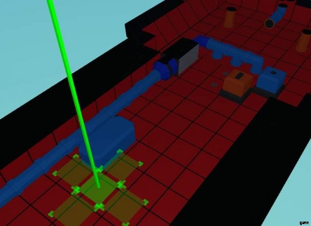
冷却装置を接続しましょう。ボートを運航しているので、海洋サイズの冷却タンクがあります。
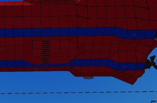
水を吸い上げるために、ボートの底に小さな延長を作りました。現在の配置で十分に効果的であり、余分なものは何も必要ありません。それは、それにぶつかるすべての海水を喜んで吸い上げます.入力を底にぴったりと置くこともできますが、このような膨らみは抗力を追加し、ボートのその部分が水から浮き上がりにくくなり、冷却海水を吸い込むためのより多くの領域を提供します.ここにポンプを設置することもできますが、必ずしも必要というわけではありません。
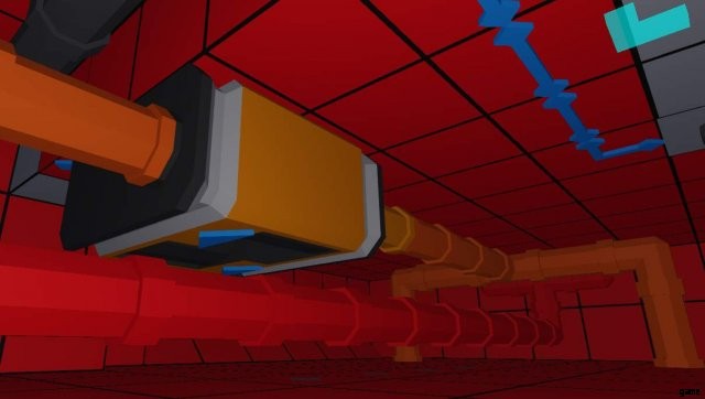
熱いクーラントを取り除くために、背面のはしごの真下にいくつかの流体ポートを配置し、そこに配管しました。私の内部は現在このようになっています.パイプの色分けは後で整理するのに便利です。ぜひ行ってください!
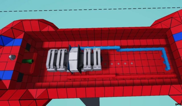
これは、完全に接続された (パワーを除く) エンジンの外観です。プロップごとに 1 つではなく、エンジンを均等に接続することを選択しました。この種のエンジンには、利点 (1 つのエンジンを失っても問題なく直進できます) と欠点 (エンジンを操縦できない、ターンでのパフォーマンスがわずかに低下する) があります。スペースは十分にありますが、パイプ管理の観点からはより簡単です。
これはエンジン設計ガイドであり、ボート ビューティー デザイン ガイド (特許出願中) ではないため、燃料、空気、排気の接続については説明しません。空気取り入れ口に空気が入っていることを確認してください。それらをどのように接続して設計するかはあなた次第です。そうであれば、燃料の量を増やすこともできます (ただし、今のところ、他のタンクは重量が大きく移動するため、空のままにしておくことをお勧めします)。
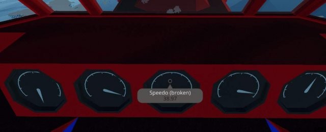
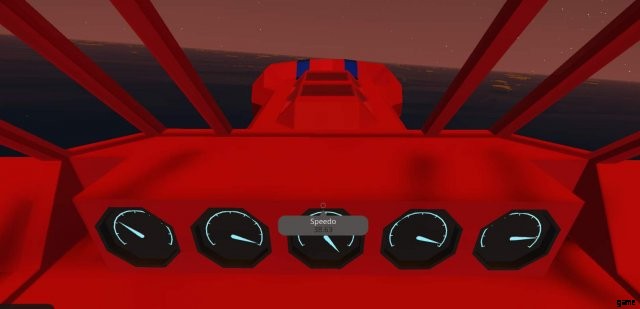
次に、エンジンをプロップに直接接続し (これはテスト目的です)、必要なすべての電子機器を実行し、最後に隙間を残さずにクラフト用のカバーを作成して、この物体が実際に浮くようにします.イグニッション ボタンがあらかじめ取り付けられています。スロットルを w/s に接続するか、必要に応じてスロットル レバーを取り付けるだけです。このもののスピードメーターは壊れています (古いため)。適切なスピードメーターをインストールするか、それがどのように感じられるかを理解することができます。試運転を行った後、チューニングを行います!
少なくともこれらを接続する必要があります:
- RPS.
- 暑さ
- 燃料
テスト結果
したがって、これらのテスト結果にはおそらく同意します:
- ものは地獄のように速く、狂っています.
- 全速力で方向転換しようとすると、災害が発生します。
- 物は最大の RPS に達し、燃料をかみ砕きます。
- 異常なエンジン ストレスにより、最終的に爆発します。
- ボートの飛行機が強すぎる
テスト結果の扱い
ポジティブな点に取り組みましょう:
- 通常のプロペラ駆動のスピードボートとしては高速です。これは望ましいことです。
- かっこいいですね。
それはすべてポジティブです。 RPS を制限することも 1 つの方法ですが、エンジンの負荷を下げても燃料消費量が増えるわけではないため、私の考えでは、より良い方法は、高いギア比のギアボックスを取り付けることです。エンジンをより低い RPS で実行します。リバースギアを得るためにとにかくこれをしたい.
ギアボックスを 1 つ取り付け、ギア比を 1:3 にして (取り付け方に注意してください)、別のテストランに使用します。目標は、エンジンが小型エンジンにとって望ましいスイートスポットである 8 RPS になるまで、さまざまなギアリングでテストランを繰り返すことです。私たちのエンジンは両方とも同じドライブシャフトに接続されているので、一方の統計を見るだけで逃げることができます.
審議中
1:3 ギアボックスを使用すると、必要な RPS の約半分に到達することに気付くはずです。当然、半分のギアが必要だと思うでしょう?これらは曲線上で機能するため、それほど単純ではありません。 1:2 (33% 減) に調整して、効果を確認してください。
1:2 ギアを使用すると、10 RPS を超えることができます。これは、実際には 1:1 ギアリングよりもこれらのプロペラでより多くのパワーを出力していることを意味します。速度は 30m/s に達しましたが、非常に制御不能でした。これら 2 つの間にはギアがあり、反対側の結果としては望ましくないため、そのギアを選択して 5:2 に乗ることができます。
結論
これらの設計により、ギアの適切な妥協点を決定し、比較的まともなスピードボート用のかなりまともなエンジンを作成しました.比較的少量の燃料を使用してかなり堅実な性能を発揮し、実行中は一種の安定性があります.
でも…もっとうまくできるはずですよね?この宇宙船はまた見られます。
ボート エンジン (ディーゼル電気) の設計
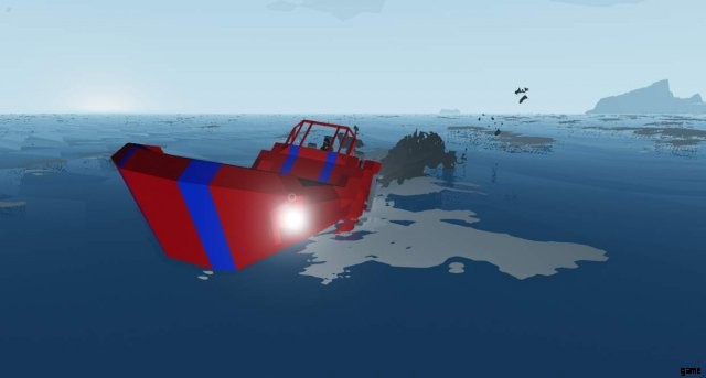
このかわいいディンギーをベースにしています
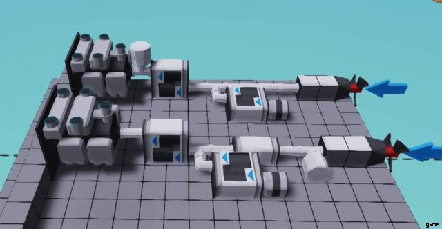
すぐにバタンと始めましょう。図のようにエンジンを組み立て、流体ポートを冷却と空気に直接取り付けます。
目に排気を吹き込まない排気管と燃料タンクでフォローアップしてください。

最後に、図のように発電機が取り付けられた 1 組のギアボックス。
電気もの!
はい、実際にエンジン (というか発電機) は完成しました。後でギアボックスを調整します。
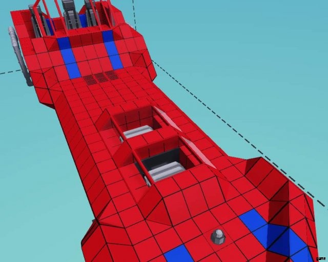
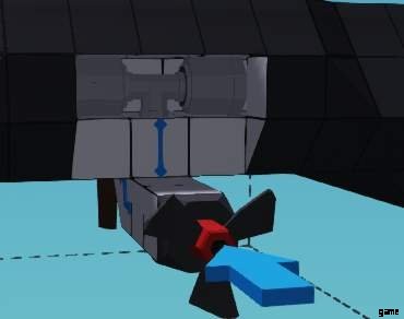
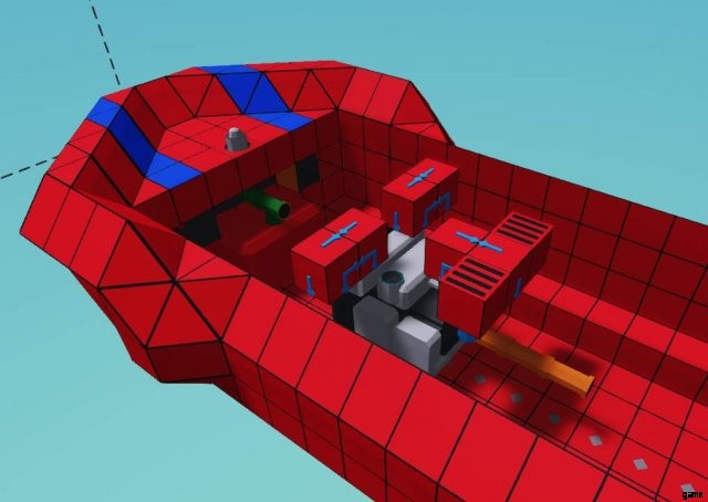
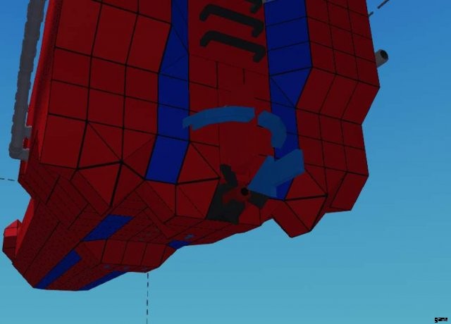
ボートの後部を開けて (内側が見やすいように内側を白くしています)、図のように支柱を取り付けます。
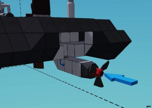
プロペラから配管して、図のように 1 組の電気モーターを取り付けます。
これが推進力に必要なすべてのスペースです。さっきの怪物と比べると、ずいぶんコンパクトですね(もちろんフロントの大きなエンジンは別として…)。ギアボックスは電気モーターにプラスの影響を与えないことを忘れないでください!
完全に終わったら、必ず穴を塞いでください。ディンギーは浮き輪に依存して水面に留まります。どこも区切られていないので、開いたままにしておくと潜水艦になります。
電気の配線をしましょう!
テストタイム!
一定数の 1 をエンジンのスロットルと始動ボタンに配線します。
ここで気になるのは、エネルギー生産とエネルギー流出の 2 つです。最初はエネルギー生産だけに専念すべきです。
必要なダイヤル (またはその他の読み取り値) は次のとおりです。
- ジェネレーターの出力 (はい、本当に、唯一無二です)
私たちが求めているもの
- 発電機の最高出力、他には?
この数値に到達するには、1:7 から 1:9 の間の比率が必要であることをたまたま知っています。あなたはいくつかの数学を行うことができますよね?数えるのが面倒な人にとっては、1:3 と 2:5 (または 1:2.5) は 1:2.5*3 または 1:7.5 で十分です。
左側には、良いジェネレーター出力として探しているものが表示されます。
テストタイム、第2ラウンド!
ラウンド2? 2 つのシステムで作業しているので、2 つのことをテストする必要があります!
必要なダイヤル (またはその他の読み取り値) は次のとおりです。
- バッテリー (ディンギーにはバッテリー マルチプライヤーが付属しており、バッテリーの % を読み取ることができます。非常に便利です)。
- 燃料容量 (使用している燃料の量を判断できるようにするため)
さて、探しているものを決定する前に… 電気モーターの 1 つを座席に直接配線し、バッテリーが約 80% になるまで乗り、それから発電機をオンにして、乗り続けます。
このミニテストで示されたのは 3 つのことです:
- 電池自体はすぐになくなります。
- 発電機は必要以上の出力を出します (これがモーターが 2 つある理由です)。
- 燃料の使用量はごくわずかです。
私たちが求めているもの
このようなシステムでは、エンジンの発電を 100% 近く (または、より多くの出力と引き換えにあちこちで短い一時停止をしても構わない場合はそれ以上) にできるだけ近づけたいと考えています。
両方のモーターを配線して、乗ってみましょう。
このテストで示されたのは 2 つのことです:
- 燃料の消費量に影響を与えることなく、はるかに高速です。
- 電池が消耗しています..
これは基本的に、スロットルをモーターに分割する必要があることを意味します。負のバッテリーのデルタ (差) に基づいてスロットルのバランスを取るやや複雑な自動システムがなくても、いくつかの知識に基づいた推測を投げるだけで、この数値を得ることができます。
ディバイダー マイクロコントローラーをディンギーの浮揚部分に残しました。このフィギュアは、走行中にバッテリーをわずかに消耗するように調整する必要がありますが、印象的な航続距離も確保できます。
それで、私たちは何を学びましたか (おそらく):
- ディンギーが滑らないように前部のエンジンが支えています。
- プレーニングをしないと潜在的な速度が低下しますが、乗り心地がはるかに安定します。
- ジェネレーター システムの作成はとても簡単です。
- 発電機は燃料をほとんど使用しないため、推進システムを実質的に隠すことができます。
- 発電機のないバッテリーはすぐになくなります。
ボート エンジン (電動アシスト) の設計
では、このシステムの奇妙さについて少し説明しましょう。
電動アシストは、すぐには多くの利点がないように見えるため、理解するのが少し難しく、セットアップする方法が複数あるため、さらに混乱します.基本的に何が起こるかというと、エンジンの出力の一部を発電に使用し、それを使用してエンジンをより高い RPS で動作させることになります。
うまくいかないようで、オーバーユニティであるように聞こえますが、エンジンにはパワー出力のスイートスポットがあり、簡単に言えば、エンジンを回転させるほど、より多くのトルクが出力されます。曲線。私が言及し続ける「スイートスポット」は、エンジンごとに異なります。小型エンジンの場合、問題のパワーを出すために燃料をあまり使用しない約8です。スターター モーターと同様に、電気モーターを使用してエンジンを強制的に回転させます。
二次的な利点は、この機能の必要性として、他のシステムにもかなりの電力が供給されることです。
この種のエンジンには 2 つの主なセットアップがあります:
エンジンに直接接続されているもの (上)。これは、バッテリーへの影響を抑えるために電気モーターのスロットルがしばしば制限される場所であり、発電機に与える必要がある量を減らします。
エンジンがその出力の半分以上を提供し (エンジンと電気モーターの間のクラッチによって調整されます)、電気モーターのほとんどが出力に直接接続されている出力に接続されているもの。
この種の設計は、頻繁に逆転する必要があるシステムで役立ちます。そのため、エンジンと出力の間のクラッチを無効にするだけで、エンジン出力の 100% を発電機に、モーターの 100% を出力に与えることができます。 、ギアボックスなしのリバースを可能にします。これは、ハイブリッド システムとしても機能します。
まだ考えるべきことがいくつかありますが、少なくとも 2 つのコンポーネントとその癖だけです。
ジェネレーター:RPS に依存し、回転ごとにより多くの電力を供給しますが、欠点として、回転が増加するにつれて回転ごとにより多くのトルクを必要とします。これは以前はなかったので、オーバーユニティ ジェネレーターを簡単に作成できました。電気を作るためだけにエンジン出力を奪いすぎないように、このバランスを取る必要があります。
モーター:バッテリーの充電量が多いほど、出力が大幅に増加します...このゲームの電気システムは少しばかげているためです。それらは 100% のバッテリーで 100% を与え、50% のバッテリーで約 40% の出力に落ちます。 %。これは単純に、より多くのバッテリーとより大きなバッテリーが必要であることを意味します.
ワッフルをやめて、構築を始めましょう
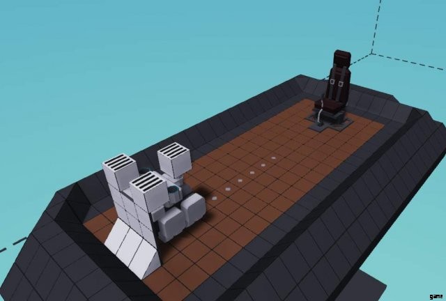
最初のエンジン設計と同じスピードボートの設計を使用するので、まだ行っていない場合はそこからワークショップのリンクを取得してください.私たちの目標は、小さなエンジンを 1 つだけ使用しながら、同等のパフォーマンス (!) に近づけることです。
何度も繰り返さないように、エンジンの接続については説明しません。燃焼セクションとまったく同じ方法で行われるので、ギアボックスや特別なものなしで完全に接続し、密閉してください。スピードボートに乗って試乗。その上、このガイドには十分なテキストがあります。以前と同様に、取水口などの設計上の決定は完全にあなた次第です。
テスト結果
ここで要因について少し考えてみましょう:
- 速度は良いですが、制御が少し難しいです。
- エンジンの RPS が上限に達しました。
- エンジンがすぐに熱くなる
- エンジンは大量の燃料を消費します。
ギアボックスを導入して、まずこれらの問題に取り組みましょう。時間と労力を節約するために、ここでのギアボックスの適切な妥協点は 2:3 の比率です。これにより、エンジンは 10m/s をわずかに下回る速度で 9 RPS になります (これらの値を知ることはチューニングに重要です)。今のところすべての問題に対処し、速度を落としていますが、これは一時的なものです.
あのボートを電化しよう!電気は水に対して非常に効果的です!
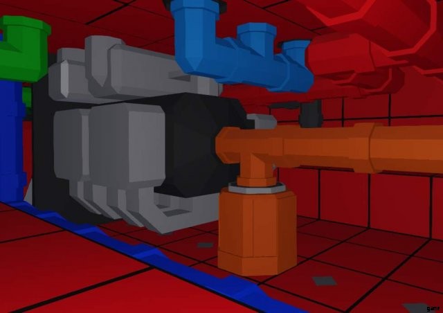
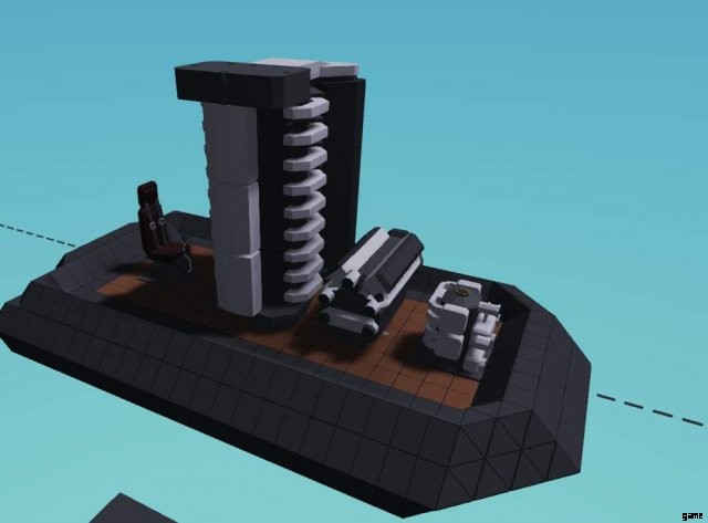
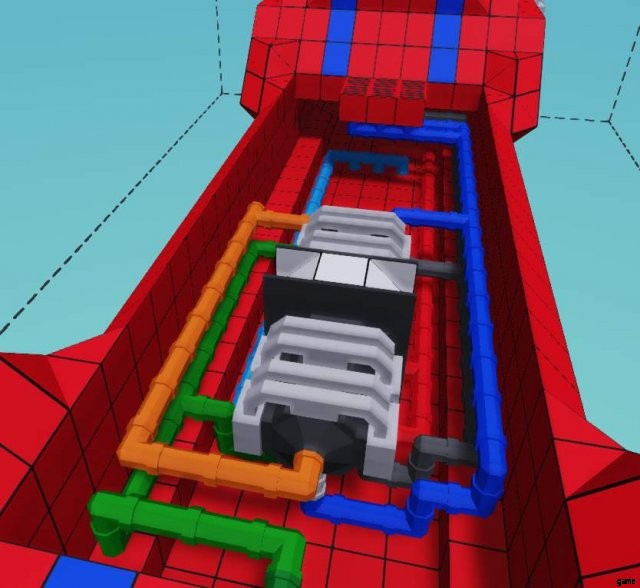
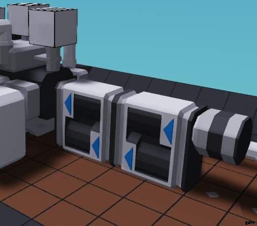
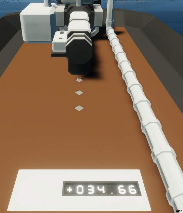
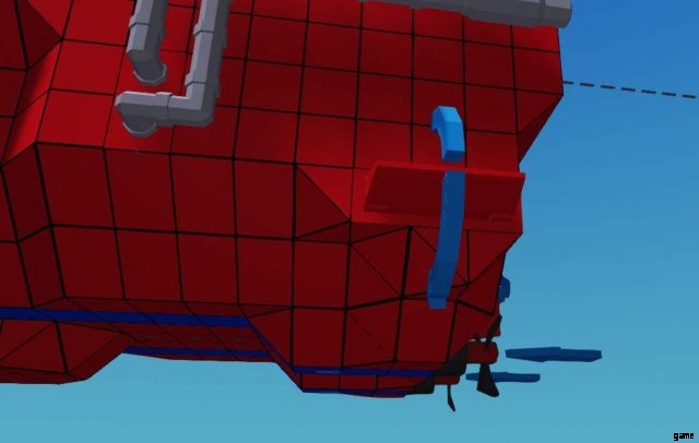
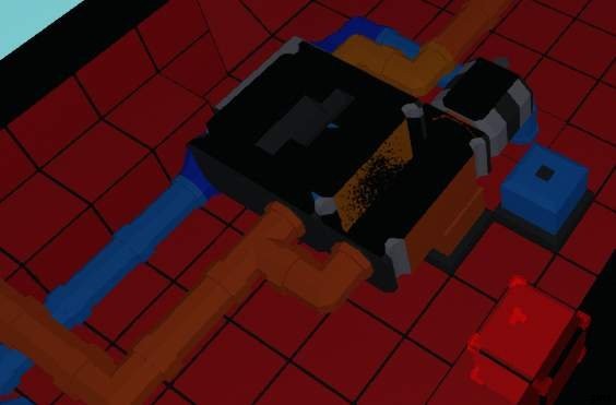
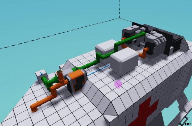
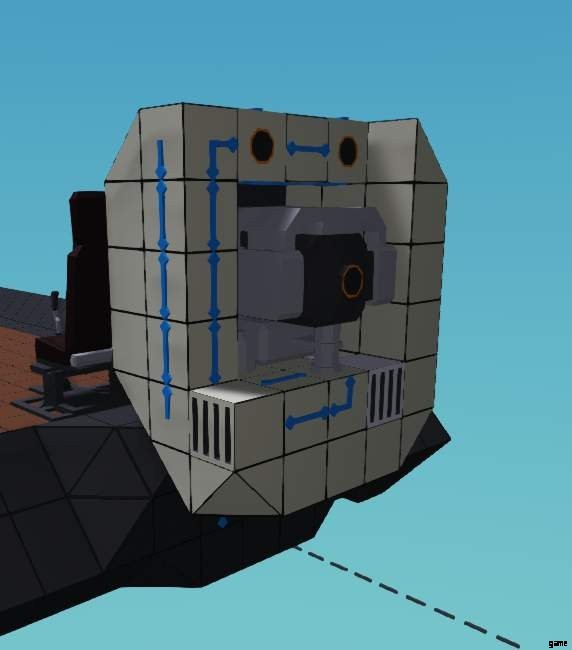
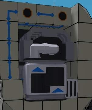
このガイドの一番上の画像に示されている最初のシステムを設計するので、エンジンの出力の横に T セクション パイプを作成し、電気モーターをその上に叩きつけます。
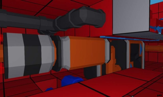
ここは少し狭いです。
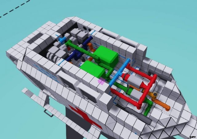
次に、現在存在するギアボックスの背後にある発電機につながるギアボックスとクラッチ システムを作成します (可能な限り多くの RPS が必要なため)。
それでは配線してみましょう
発電機に 1:3 の比率を設定し、電気を接続しながらクラッチをスロットル レバーに接続します。スロットル レバーは一時的な手段であるため、自動化されたシステムを作成しなくても、これに適したクラッチ比を見つけることができます (これは優れていますが、ガイドするのは困難です!)。
また、エネルギーを使いすぎないようにモーターのスロットルを半分にしたいので、スロットル入力を 2 で割るか、0.5 を掛けます。これは、エンジンを制御しているスロットルと同じなので、w/s を使用している場合はそれに配線してください。
テスト結果、ラウンド 2!
では… 100% ジェネレーター クラッチを使用していても、バッテリーが消耗しているのはなぜですか?
この場合、実際にはエンジンを強く押しすぎているので、ボディを少し変更する必要があります。後部のツイン プロペラを取り外し、代わりに中央のプロペラを 1 つ取り付けます。他に何も変更せずに、テストを実行してみましょう。
テストの結果、三度目が魅力!
エンジンを大幅に強化しました。現在は 12 ~ 13 RPS に達しており、より高速に到達できますが、それにもかかわらず、以前より多くの燃料を使用しているようには見えません。バッテリーの消耗はまだかなり高いので、発電機のクラッチを絞る前にエンジンの回転数を上げて発電を開始する必要があります.
では、常に手動でクラッチをいじる必要がない解決策をどのように考え出すのでしょうか?簡単なことを試してみましょう。ピーク RPS が約 12 であることはわかっているので、約 0.75 クラッチの数値が必要です (さまざまな値をテストし、バッテリーの値を確認しながらしばらく運転することで、適切な妥協点を見つけることができます)。
12 割る 16 は 0.75 であることが判明したので、エンジンの RPS を接続して発電機クラッチを制御できます。RPS を 15 で割れば、RPS を 15 で割ることができます。エンジン性能。波がボートを揺さぶり、RPS が跳ね返るので、少し余裕を持たせる必要があります。これは、バッテリーが確実に充電されるようにするためです.
結果!
セットアップがより複雑であるにもかかわらず、ツイン燃焼エンジンで同等のパフォーマンスを得ることができました。実際には、より少ない燃料を使用し、エネルギー生成を適切に行っています。おそらく、フラッドライトを 1 つまたは 2 つ永続的に稼働させるのに十分です.
エンジンのRPSがおそらく私たちが望むよりも高く、燃料消費量をさらに減らすことができたとしても、私たちの目標は、以前に設計された双発パワーボートの性能を達成することでした
このシステムは、ツイン エンジンのセットアップにも適用して、さらに強力にすることができます。
The Boat Designs Extra Credit
その絶対にひどい Youtube シリーズとは関係ありません。
このセクションでは、ボートをさらに良くするためのいくつかの作業を行ういくつかのトリック (エンジン設計を超えたものもあります) を示すことで、さらに詳しく説明します.
双発機に最も多くの改善を加えることができるので、私はその特定の機体に対処します.電気駆動ディンギーに関する限り、それに対して実行できる唯一の真の改善は、発電機エンジンを 2 倍にし、仕切りを取り除くことです。
この機体には他にも調整が可能です。たとえば、電動アシストを付けたり、エンジン出力を分離して 1 つのエンジンで 1 つのプロペラを駆動したりできますが、簡潔にするために、それらについては説明しません。
これらすべてがこの 1 つのサンプル ボートで行われているにもかかわらず、ここで使用されている方法はほとんどのタイプのボートに適用可能であり、数と詳細は異なりますが、原則は同じままであることに注意してください。
審議
しばらく行っていない場合は、ツイン エンジン ボートを試運転して乗り心地を確認し、ギアを 1:2 に落としてリミッターを外した後に改善できる点を判断してください。これが機体を改良するための基本であり、その中で走り回り、何が改良できるかを考えます。
- ボートをひっくり返さずに高速で方向転換するのは非常に困難です。
- エンジン RPS が 11 ~ 12 前後になると、ボートの滑走が激しくなりすぎます。
これらは、現在最も差し迫った問題である非常に明白な欠点の 2 つです。それらを修正することに集中しましょう
データの修正
このセクションはすべて、Mr. Plinkett の美声であると想像できます。ミスター・プリンケットが誰だかわからないなら、私はあなたを教養がないと考えますが、それはまったく問題ありません。
安定性の向上
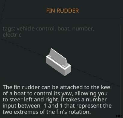
Stormworks で最も魔法のような作品の 1 つを紹介しましょう。水に導入されたときのフィンラダーは、非常に強力な方法で角運動に抵抗する抗力の怪物であり、さらに、それを利用するために、ほとんどの場合、電力さえ必要としません.
図のように取り付けるだけで、電気などを接続する必要はありません。今すぐ試乗してください。どうしたの?
おっと、速度が 2 倍になりました。よし、じゃあ。
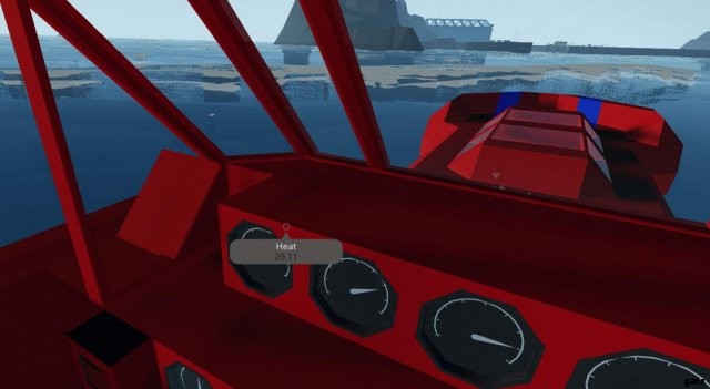
冷却の改善
冷却を改善していないエンジンは、安定した波のない海で約 105 度にとどまっていますが、空気を取り込み始めてエンジンが 15RPS を超えると問題が発生します。残念ながら、これは速度の向上のほとんどが得られる場所でもあるため、ジレンマがあります:
解決策 1: 簡単な解決策:両方のエンジンでエンジン RPS を 15 に制限します。バム、これで終わりです。
解決策 2

スピードボートの底でかなり大きなスクープを作ります。私のように2つの深さである必要はありませんが、これにより、すぐに水を吸い続けることが絶対に保証されます.これは抗力を増加させ、もちろん速度に影響を与えますが、余裕は十分にあります。
次に、それをエンジンの冷却パイプに接続し、ポンプを配置して流体の流れを一方向にし、冷却システムに圧力をかけます。とりあえずこのポンプは常時オン信号で強制的にオンにしましたが、後でスターターキーに接続したほうがよいでしょう。
Then make a small (or 2, or 3) liquid tanks filled with water connected to the cooling pipe with T-pieces, these are reservoirs for the coolant, which is consumed very quickly for the 2 engines. They will be useful when we bounce around with waves, so the engine will never be left without cooling.
While not really an absolute need, now would be a good time to install an generator. Place it before the gearbox and place it behind a clutch permanently stuck to 0.5 or so. This means it’s taking only a little bit of our engine power and keeping our batteries charged. Unfortunately the picture is somewhat unclear, as cutting the boat in half cuts out the top of the components.
That should keep it in check. The engine heat doesn’t really go high above 30C° now.
Forcing planing
We use the very same magical part from the first section, the rudder.
We’ll be placing it somewhere along the bottom, depending how much we want to plane. I’ll put it right around here, though adjusting its position later for further testing is a good idea. Then attach a throttle lever to it, and set the throttle’s range between 0.1 and -0.1. Don’t forget to give it some electrical juice.
Now, what we will be doing is taking it for a ride, we’re looking for a value to permanently bind to it where we plane, but we don’t become unstable. It is also possible to make this reactive, so it only activates at speed with a microcontroller, but given with how many images and deep explanations i need to give with microcontrollers, i’ll pass on that, sorry!
Planing without being a plane
For me, the value for stable, non-planing is with about 90% throttle and 0.1 (note that the rudder will be pushing the nose down with this value because of how it’s aligned in the picture), and 0.05 will allow it to plane while keeping it steady.
Around 80 knots for a speedboat isn’t too bad, is it?
Exploding less dinosaurs
Ah yes, fuel economy. This one’s easy after all those.
- Return the gearbox to 9:5
- Find a value for the front fin rudder where it provides lift so you can plane, for me it was -0.1
Exploding more dinosaurs!
That’s infeasible, but if you really want it to give all of its performance, move the RPS cap of the engines to 28 or so. It will be very very unstable without any electronic stabilization, and it would take a section of about the size of this whole section to explain. I can only wish you good luck, you absolute madman.
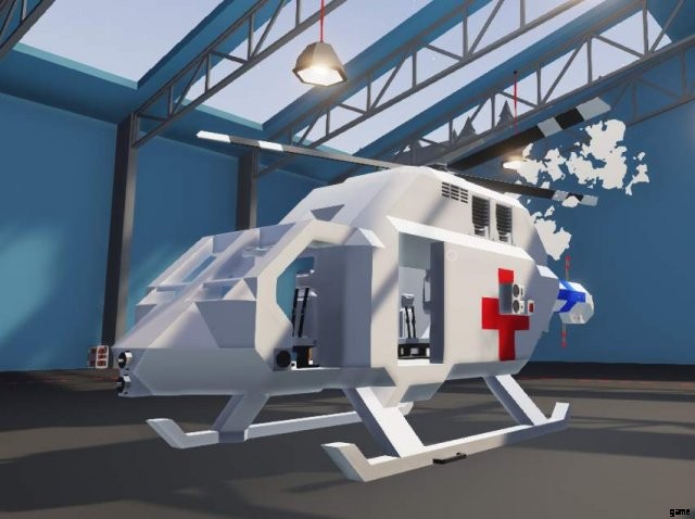
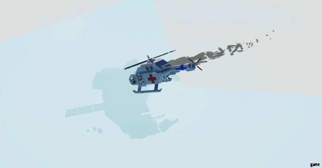
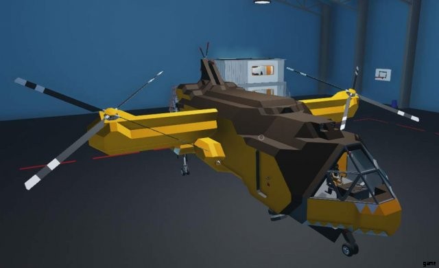
Designing an All-Around Helicopter for Medical &Rescue
Well, it’s finally here (this statement will age well after i’ve put in all the other sections, won’t it?) the helicopter.
- Here’s a war crime for you to use.
No, really. I’m not kidding, apparently using the red cross without proper authorization is a violation of the Geneva convention, which makes it a war crime! You learn new and interesting things every day.
No, i didn’t opt to remove it, because i’m an Egyptian sun god. (Unless i’ve changed my Steam name at the point that you read this, then just imagine whatever is appropriate)
Jests aside, this is, without any jokes, the hull of the first helicopter (well, second revision of it) that i ever made in the game. I’ve stripped off pretty much everything out of it, so you only have the hull to work with. I’ve even removed all the connections, because i’m a terrible person! Some just want to watch the world learn…
But… what’s a helicopter?
You know those things called airplanes? They’re called “Fixed wing aircraft”, do you know why? It’s because their wings don’t flap, move, turn, or anything like that. They depend on something pushing them so that the air moves over the wings which are designed to generate lift which makes it so that when the plane moves fast enough, it’s pulled off the ground. Amazing, huh?
Helicopters are rotary wing aircraft. They’re called that because some complete genius decided that instead of having wings like planes… what if… you put those 2 wings on top of the plane, and instead of something like a prop engine pushing the plane, what if we just spun the wings around? I’m sure that ended in some sort of a massive explosion and fireball, but somehow we ended up with the helicopter as a result.
“But i didn’t ask that, you’re just putting words in my mouth!”
Oh by the way there’s going to be an unusually large amount of theory in this section, because understanding how helicopters, and their props work is the key to making a good one. Thankfully the previous section takes care of a lot, so let’s actually do something concrete.
Let’s build stuff before you get bored of the wall of text
Make this extremely crude addition to the helicopter, the components in question are a throttle lever and a tail rotor
“But that’s not a propeller, and that’s not where a tail rotor goes!”
Shush, don’t make fun of the tail rotor’s size or where it’s situated. It’s a perfectly capable helicopter rotor in its own right. Plus it’s easier to fit on there. Link up the tail rotor’s Yaw to the throttle lever, and wire up some electricity for the throttle lever. Change the throttle lever’s properties so the range is -1 to 1.
Now just go ahead and play with the throttle for a while. You see what the rotor’s blades are doing? This is something that’s called the collective. Also super secret amazing hidden feature:click E or Q on the tail rotor to fold it. Magic.
Nobody expects the Spanish theory section… especially when it’s written in English
“But i thought that was the theory section…”
Yes, sorry, it wasn’t, but i promise this part is actually shorter than you think.
Collective is nothing but the attack angle or prop pitch, but for helicopter rotors. It’s actually simpler than apparent:The higher the collective, the more lift the prop provides. This also means that it has more drag, so the engine has to give out more torque to rotate it.
The reason i’ve asked you to also hook in negative, is because negative collective (in case of tail rotor, helpfully labelled yaw) is also a thing. This allows you to turn left and right with the tail rotor, or make an upside down propeller provide upward lift.
If you’re unfamiliar with the “six degrees of motion” terminology, here’s the simple explanation:
- Yaw:Turn Left or right
- Pitch:Tilt up and down
- Roll:Tilt left or right
“Can we stop with the theory now?”
No, because i’m ending this section. Ha-ha, the building part you were looking forward to was in the next section all along! Now you know how Mario feels when he finds Toad instead of Princess!
Also delete that tailrotor and throttle from the side of the helicopter, we won’t be needing them.
Designing an All-Around Helicopter for Medical &Rescue pt 2…ish, But Not Really
First things first, let’s examine the helicopter. The particular importance, like with the speedboat is the center of mass.
“Wait, is this another theory section? I thought you said…”
Super quick, super important, ok? No funny stuff, i’ll just get it out of the way, deal?
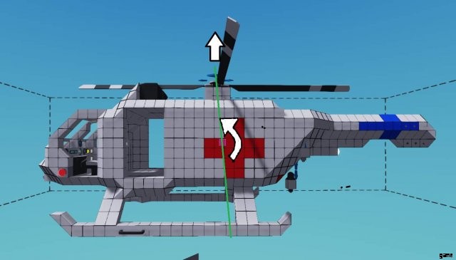
As this highly professional MS paint shows, because this is a pulling, instead of a pushing type of motor (unlike the speedboat for instance) the force on the imagined “lever” is a more rotational type force that forces the nose to pitch down. Imagine like you were dragging it around on a string. This is what the force is like.
Misaligned center of mass also causes a significant amount of instability, so it should be of utmost importance to try and align these as much as possible for any helicopter. The batteries are situated where they are to try and adjust this balance.
It should also be of note that when fuel drains, it can easily shift this center of balance, so fuel tanks should be situated in line with center of balance.
Now let’s actually get to building
Since this is a general purpose helicopter, and comes with a winch, a single diesel engine lacks power to carry stuff, but would be OK for ambulance only. If you only care about range, want to make it lighter and a medical rescue helo, you can follow this guide by building a central single engine instead.
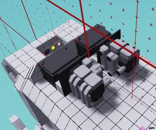
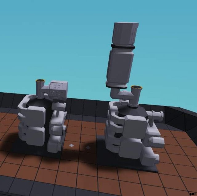
My personal preference is to make the twin engines in designs like this “kiss” eachother. One tile gap between them allows extremely compact engine designs without compromising utility. As before, this isn’t really a pipe beauty guide or anything like that, so i’ll walk you through the less obvious ones:
The fuel pipe has a fluid intake situated on the back-end of the craft. A rear-mounted single pump is useful to have for pushing the fuel all the way to the tanks. It might not be a necessity, but it really isn’t a problem on electricity drain either way.
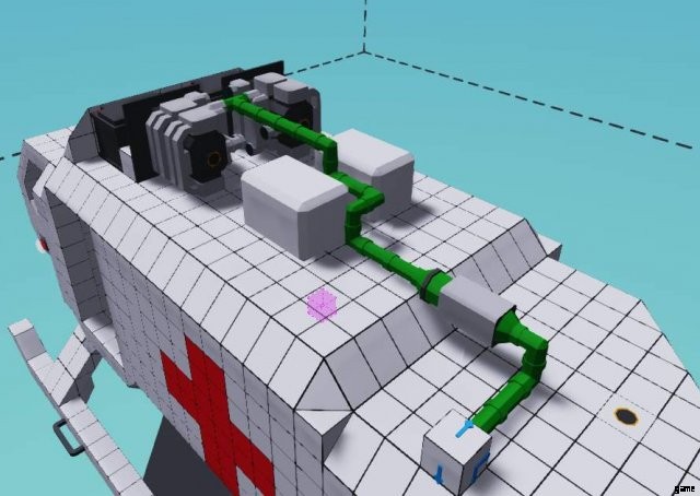
Hook up the drivetrain to the already existing tail and introduce a gearbox along the way, where and how is up to you. The tail exists already for your convenience, and has a sneaky little generator behind a clutch so we can keep electricity topped up.
How you design the rest of the engine bay, including cooling and air intakes is up to you. This will not use a lot of cooling, the double radiators i used are mostly for aesthetics (and possible future tuning). What’s important is that you have all that you need hooked up.
Now would be a good time to hook up that engine by locking its throttle to 1 with a constant number and giving it a go. It’s easy at this point to see the engines still so you can tell what issues (if any) they have. Though you could also just remove a part of the interior ceiling to see them, i guess.
My engines stabilize at around 93 and 91 degrees. There’s often some weird variance between 2 sides, up to even 10 degrees. Don’t let it bother you.
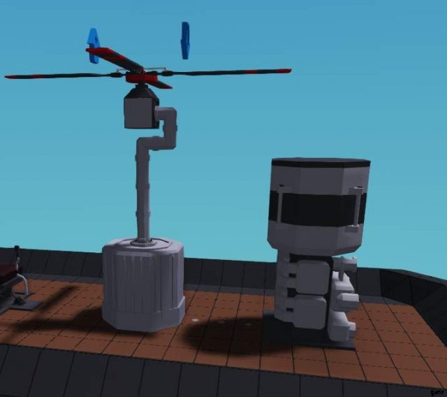
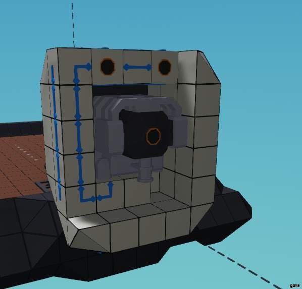
The crown on top of the helicopter
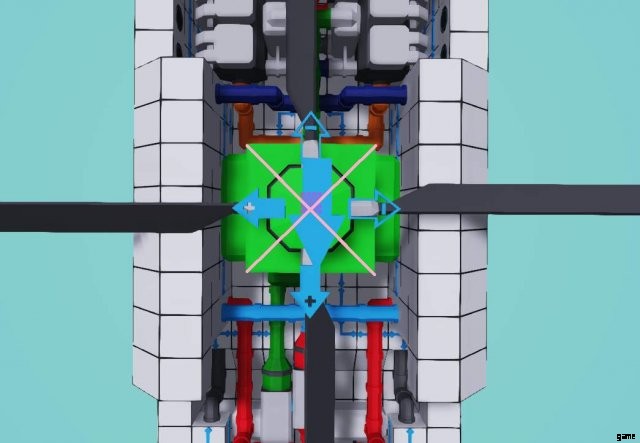
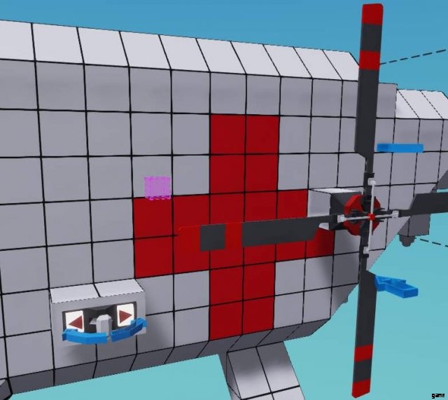
Finally, it’s time to put the cream of the crop on the top. Make very sure the large rotor is as close to in line with with the center of mass as possible.
In the picture of mine you can see i drew a pink X on top of the rotor housing. You should notice 2 particular things:
- The large arrow is nowhere near centered and is a poor indicator for it being near the center.
- My arrow is pointing backwards.
The latter just means i will have to inverse my inputs with a multiplication of -1. This is the only time in the guide i will refer to this, as it’s very possible with your engine design you can simply place your rotor the right way round.
Hook up the rotor to the drivetrain behind the gearbox, then do the last bit of covering up of the engine and beauty work, because the engine is going away now. We won’t be seeing it again unless we need to work on it again in the future. Finally, sneak a tail rotor in place, there’s a pipe eagerly waiting there. You can install rudders if you’d like to have them.
This is a good time to test those engines again.
Sure, it looks like a dopey humpback, but it’s done from a mechanical standpoint… but why doesn’t it fly even with the prop at positive (locks collective to 1)?
A sneaky anecdote
So, there’s 2 different types of helicopter:
- Old style: The prop is completely locked on positive, and engine throttle determines how much lift is gained.
- Modern: The collective is variable and determines the lift, and electronics control the throttle to keep it at a desired RPS.
There’s up and downs to both of these systems, the old style is more reliable, as there’s less moving parts, but the modern is significantly more flexible and responsive to input as it doesn’t rely on throttling a combustion engine.
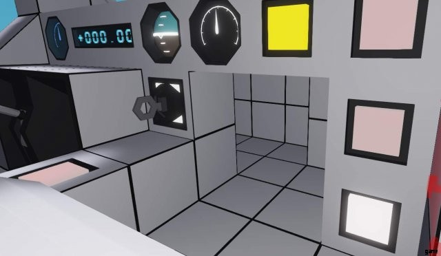
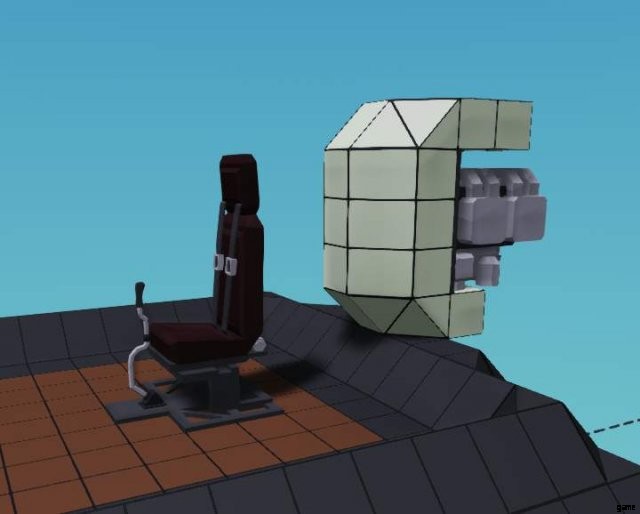
Wiring it up
You will find a lot of the cockpit pre-wired (and mysterious nonfunctional controls for other stuff that aren’t there, hmm), the main part we’re interested in is the gyro already installed at the back of the seating compartment.
As doing an electronically controlled engine requires significant electronics, i will leave that for extra credit, along with a few other things. We will be making an old style one.
First, install a throttle lever to control the engine throttle, then wire up these inputs on the gyro:Roll, yaw and pitch, leave the up/down alone. Oh, and something to start the engine would be nice. Finally slap the gear ratio of the gearbox to 1:2.
After doing all that, wire the stabilized output of the gyro to the relevant outputs. The yaw goes to tailrotor, pitch and roll go to the rotor above. You know that part which i said i won’t bring up? I lied. This is just a friendly reminder that if your rotor is backwards, your stabilized(!) pitch and roll are reversed. Likely your stabilized yaw is also reversed with how the tail rotor is faced.
You may play with stuff like the ratio later on your own, the reason i’m not going into more detail and explaining the choices better here is because i’m running close to the size limit of this section of the guide. I will save more of the detailed explanation for the extra credit part.
Test run? Test run!
Quick troubleshoot:
- Does it just roll like a washing machine tumbler?
- Invert the stabilized roll going to the rotor
- Does the engine blow up?
- Limit the RPS lower than 20
- Does it stutter weirdly at high throttle?
- This is engine tremble, because the engines are peaking out with their RPS and responding to the changing load while they’re spooling up their own rotations. It’s an unavoidable part of using this old style hookup. You can get rid of most of the engine tremble corrected by the gyro by dividing the stabilized roll input by a relatively large number, like 5, but this is fixing the problem and not the cause.
Those are the only problems that are really possible for this setup…
Finally, test at what point it lifts off. For me it’s 0.55. It might be wise to set the minimum throttle slightly below this for a good landing setting, something like 0.53 worked for me. It is an absolute power house, but with the rather difficult throttle control it’s really not easy to handle, but it most definitely flies, and it flies hard.
In other words, a perfectly functional helicopter, good job!
Extra Credit:Engoodening the All-Purpose Helo
If Internet Historian says “Engoodening” is a word, it sure is a word!
The entire section is practically dedicated to making an electronic engine control module, and it’ll be quite light in theory, but if you can’t think with logic gates, it’ll be quite complex. Let’s get the theory out of the way:
The theory section
We want the small engines to hover around a desired RPS, and we need the throttle to be automatically controlled to do this. There’s 2 ways of doing this:
A physical throttle lever that is controlled by the electronics
- This gives us an easy to see visual representation of what the script is doing.
- In emergency situations we can have an override that disables the script from controlling the throttle.
- It’s easy to disable the automatic throttle control and turn the throttle to 0 to shut off the engine.
An internal throttle control that’s handled inside the microcontroller itself
- This is significantly more responsive than the actual throttle lever even with high throttle sensitivity.
- Requires less size as a microcontroller as it doesn’t need the 2 outputs to the throttle lever.
- Requires less space in the cockpit.
Usually i would favor the bottom one, but it does require more work to tune the sensitivity of the counter, and is generally a bit more difficult to design. We’ll go with the simpler, if still more striking option.
First things first
If you’ve followed the guide so far and are not here to look up upgrades for your helicopter, we only have a throttle control, without the up/down of the gyro being engaged. The up/down control from the gyro will control the collective of the helicopter blades to provide lift. At 0 engagement it will make the helicopter “neutrally buoyant”, or close enough. In reality this won’t be quite exact, as every helicopter and situation is a little bit different.
Here’s what we’ll do:
You can either hook up another throttle lever for the up/down adjustment in the cockpit, or simply wire it to up/down on the seat. For the throttle lever you’ll need -0.4 as the minimum for a good landing setting.
After hooking up the lever to the gyro, hook up the stabilized up/down to the collective of the helicopter blades, then make very sure to set the prop of the heli to neutral. This will allow adjusting the collective of the prop itself.
Return your throttle’s minimum setting to 0, then connect its electrics to an electric relay so that it can only get juice when the relay is on. If you haven’t used one before, it’s an electric switchbox that’s controlled by an on/off signal. We will use this to disable the manual use of the throttle lever when the override is on.
The relay isn’t absolutely necessary, and you can have a 2×2 microcontroller instead without it, but adding it won’t be much trouble.
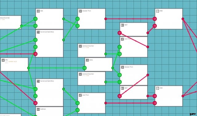
Let’s get to the electronics, with some pictures!
Let’s dig a nice hole for that microcontroller, the 2×3 space hidden behind the panel should be enough. You need to dig in there a little bit, but it’s fine.
Let’s design the microcontroller now, we’ll need the following:
- Override input (on/off).
- RPS Input (number)> one is enough, the engines are stuck on the same drivetrain.
- Throttle up output (on/off).
- Throttle down output (on/off).
- Relay output (on/off).
We’re going to use a similar layout to this. Let’s lay out our already existing pieces in a sensible manner.
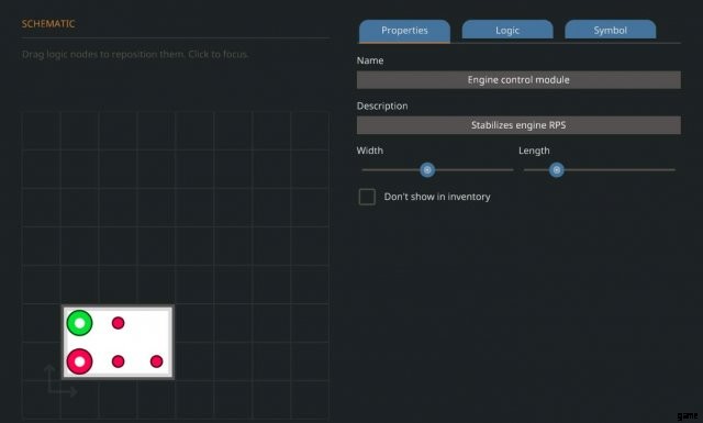
良い。 The far left will feature RPS only, because we’ll need some logic to handle it, the right hand side will feature our assortments of other stuff. We will be using the override later, so it’s off to the side.
Chips we need:
- Less than> Hopefully obvious.
- Greater than> As above.
- Property number> Easily modifiable number that you can adjust in properties.
- Add>
- Substract> These 2 modify the property number.
- 2x Constant number> Set at 0.5 so we have a desired range.
Lay them out as such
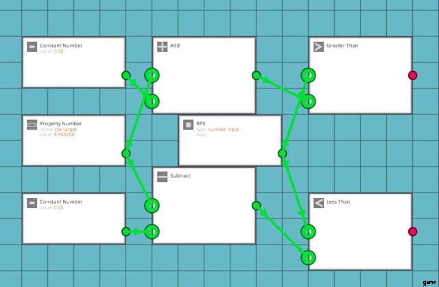
I will try to explain the logic behind these in the first paragraph after every picture, if you’re already decent with logic, you can skip this part. Firstly, we’re using 2 constant numbers only so it’s easier to read. The incoming number sets the desired target, the addition and substraction creates a range of +0.5 and -0.5 from that value, this compares the RPS coming from the engine to see whether or not it is larger or smaller than the desired value.
We can also make it so that the desired value can be determined by things like keypad input, but that’s for you to do if you wish to do that. Now that we have the comparative logic in place, let’s handle the outputs logically
Chips we need:
- Or> So that either greater or lesser than input enables the relay so that the script can modify the throttle.
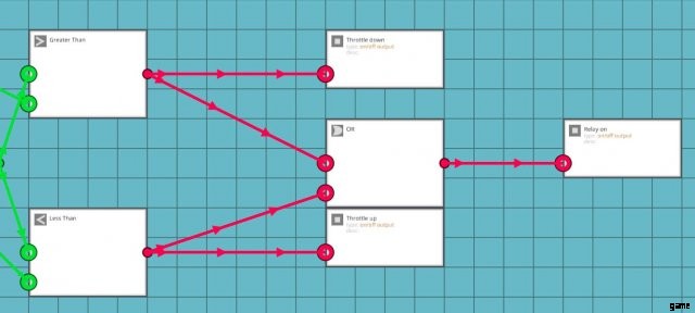
Well, that was simpler than expected, wasn’t it? This setup enables the relay whenever either greater than or lesser than condition is met, and allows the adjustment of the throttle. However, it disables the relay when either condition isn’t met (the throttle is in desired range), and thus disables you handling the throttle lever.
Ok, it’ll take a little bit of thinking to do the override properly. Our easiest way is probably to attack the numerical section of the electronics, as explaining how to override the binary logic itself would be a little bit more complicated.
Chips we need:
- 2x Numerical switchbox> We switch out the RPS input for a desired value.
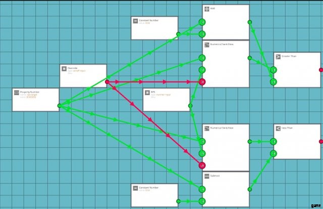
It might be a little hard to read, but the RPS values are on the “off” state inputs of the switchbox (when override is not on), and the desired number is on the “on” state of the switchbox inputs, which are linked to the lesser and greater than A ports. This means that when override is on, the electronics think that the engine RPS value is always at a desired state.
We’re still missing one little thing, forcing the override to enable the relay
Chips we need:
- 2x Not gates> Optional, i use these in pairs (they cancel eachother out) to route the signal. Makes it easier to read.
- Or> For yet another fork to the relay input.
This makes another OR-fork for enabling the relay. As you can see, the paired NOT gates makes a nice routing for the signal, instead of it just crossing over everything.
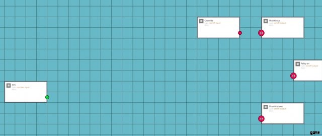
I’m sure you can figure out where and how to wire these, but just in case there’s someone who’s still very much learning english, or simply having a confused day (and doesn’t want to ask the silly question) here’s the breakdown:
- RPS takes in the RPS value of any engine.
- Override takes in a toggle button.
- Throttle up goes in to the up input of the throttle lever.
- Throttle down goes into the down input of the throttle lever.
- Relay connects to the electric relay that is connected to the throttle lever.
If you’re flying the helo made with the section above, set the desired value to 11, then set the gearbox to 1:3.
Testing time
So… it kinda works. If you gun the collective, but you soon have to hit the override and handle it yourself. What’s wrong?
What’s happening is that the script is failing to take into account that the engine is taking time to respond to the throttle input. It’s trying to adjust the throttle wanting an immediate reaction from the engine. This would work with an electric motor, but we need to look at something else.
Let’s go back to the script for one more final swing at it.
Note:This section ran out of text space, how awkward.
Extra Credit:Engoodening the All-Purpose Helo (Cont.)
One more tweak, that’ll surely do it!
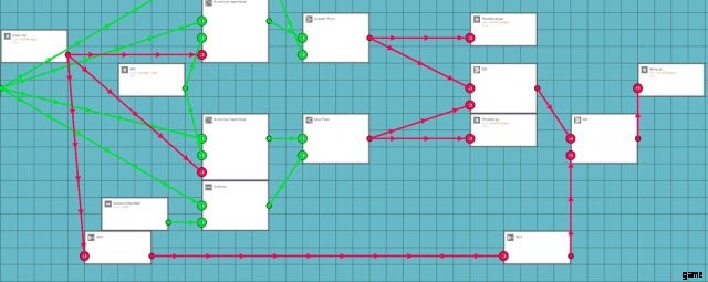
Chips we need:
- Delta> High school maths. The difference of a value given a unit of time (in this case, 1/60 of a second).
- Greater than>
- Less than> These 2 for comparisons.
- 2x Constant value> To be compared against.
- 2X and> The RPS value is below and not rising or The RPS value is above and not dropping.
- 2X not> Read above.
It’s easier to describe the logic here as the computer reads it. Remember, delta looks at the difference of the RPS value, so we will know if the engine is spooling down or up.
Here’s essentially what the entire chip does:
- If RPS is less than desired value and not already rising:Enable relay, increase throttle.
- If RPS is more than desired value and not already dropping:Enable relay, reduce throttle.
- If override is on, RPS =Desired value:Enable relay.
The 0 setting for the constant numbers is not error-free. Something like 0.01 or 0.005 would likely work better. You’d have to observe the delta number to figure out what’s a good value for it. Calibrating this value is pretty engine setup specific, but it won’t take too much trial and error to figure out. All it takes is making a temporary number output and getting the readout on the delta value on something so you can watch the decimals work.
Let’s test again, like we did last summer
おい! If you wired up everything correctly, it’s perfectly functional now. It responds relatively fast, and stabilizes the engine by throwing the throttle around.
The only problem with this is that it does so little bit too eagerly, this is mostly a very mild annoyance type of problem, as it revs the engine up and down to keep within the target. The only way to deal with this particular problem is to make another logic section that handles the fine adjustments of the throttle lever itself. Basically this is what you need to have:
- If RPS is within +/0.3 of desired value:Do very short touches on throttle to find the sweetspot.
- Something more reactive likely works best, like:
- If RPS is less than 0.3 more than desired value and delta is above 0, reduce throttle for X amount of ticks
- If RPS is more than -0.3 less than desired value and delta is below 0, increase throttle for X amount of ticks.
This i will leave for you to figure out how to do, but i’ll say it isn’t very difficult to do. I’ll give you a hint:The timer logic blocks allow you to configure them to output things for X amount of ticks, you can multiply the absolute (removes negative) delta value to get an exact adjustment for desired throttle, but it’ll need some trial and error. You probably want the timer that outputs when it is less than its set duration. If you want one-tick adjustments and can’t figure out how to deal with the clocks, a combination of toggle to push and blinker allow you to put out 5 or 10 signals per second as opposed to 60. Or, you know, you could just use a PID, but where’s the fun in that?
Success!
Extra Badly Designing a Combustion Engine for Boats
This section is mostly meant for what it looks when you design a section of a guide without testing the concept firsthand. I left it in as a curiousity more than anything else, please do not follow this for your sanity’s sake.
Let’s start building. My outboard will be slightly creamy with red racing stripes.
The engine should be seated so that the coolant in/out piping is either in line, or one behind the last block on the Dinghy. Yes, it will be comically huge because we’re using the “small” diesel engine, but this is fine.

This is an easy way of dealing with cooling. If you want a rotary version of the outboard, you’d have to integrate the cooling into the downward reaching part of the outboard with the prop, but it’s relatively easy to pipe.
When dealing with exhaust and fuel, we should bulge out the outboard’s cowling (the shell of it) so we can hide encased piping where we want it. This was my design of choice, but you can just pipe it out the side as well.
This is my solution for the air intake. Unsurprisingly, the most important feature of the air intake is to take in air, but at the time of writing the engines don’t care if water gets in it even for a good while, you don’t need to make a filtration system.
For the tank i would use a custom enclosed tank, but since this is attached to a dinghy and the weight would be absurd, i’m in fact going back on that design and just tucking on a small tank, as it’s enough for testing, and for later use the outboard can be taken off and used as a subassembly!
Finally, we should hide a gearbox in the bulky form of the comically huge outboard engine.
Make sure that the gearbox’s arrows are pointing toward the engine, since we want to increase the RPM.

Then finish the rest of the cowling and make sure the damn thing floats.
Testing time!
Now as said before, we’re working technically against a constant load. So wire that sucker up in any way you like, try for 2 gear ratios that sound feasible to you (like 2:3 and 1:2) and prepare to test it out.
Here’s the dials (or other readouts) that we want:
- Engine heat (optional, but good to see).
- Engine RPS (absolute must for fuel economy tuning).
- A visible way to see whether or not the gearbox is toggled on.
- Fuel tank’s contents.
- Speed.
What we’re looking for
Signs of the gearing being too low:
- RPS increasing above 8 on a small engine (unless you don’t care about fuel efficiency, then 10-12 RPS is a good target).
- The boat becoming unstable (this can be addressed with hull design).
- Excessive fuel consumption.
Signs of the gearing being too high:
- Excessively slow start (slow start is ok, since we have 2 gears to play with we can use the other one too).
- RPS stays constantly below 6 even after reaching full speed.
- It doesn’t start at all (very hard to do in a boat).
After flipping my boat a few times with the excessively heavy outboard, i’ve come to a value of 5:9 for the gearbox being perfect. RPS sits around 7.2 and rises up to 9 if i catch some air, but never enough to flip the boat if i feather the throttle a little bit. It can reach about 10m/s before becoming unstable.
So what have we learned (possibly):
- Heavy outboards on small rubber dinghies are dumb and cause it to flip.
- If there was more weight toward the front of the craft, we could go faster without flipping.
- Getting that right gear ratio for a boat requires a few test runs, so it probably should be done last.